|
Nov. 18, 2021
coronary

Optimal Guide Catheter Support With Silverway
Principal
The ASAHI Silverway is a high performance angiographic guide wire based on the 0.035” platform. A typical characteristic is the trackability of the wire to negotiate and cross complex arterial architecture. This trackability comes from the flexible Silverway tip that accurately follows the path line of the arteries. A logical consequence is that specific tip part of Silverway provides less support for the guide catheter(GC) in use.
The distal flexibility of Silverway should not be perceived as a trade-off, having lower support provided to the GC. The user only needs to apply a simple wiring approach to benefit from the high trackability and have the superior support for the GC. To benefit from the flexibility as well having high support, the user must reassure that Silverway is placed or used in such a way, that the high supportive part is positioned in the GC.
To utilize the high supportive part of Silverway for an effective movement of the guiding catheter, Silverway must be pushed far enough out of the GC tip. With this strategy the flexible tip is in front of the GC, and the high supportive part is in the lumen of the GC. This will lead to an optimal straightening of the GC curve, and the highest support to guide the GC trough complex arterial anatomy.
The technical explanation for this wiring approach is that the first 15 cm of the Silverway tip is made highly flexible for high performance tracking through arteries. Thus, beyond this point the rigid and supportive part starts of the guide wire shaft. Meaning in practice that for having the highest support for the GC, it must be placed at least 15 cm from the tip.
Example
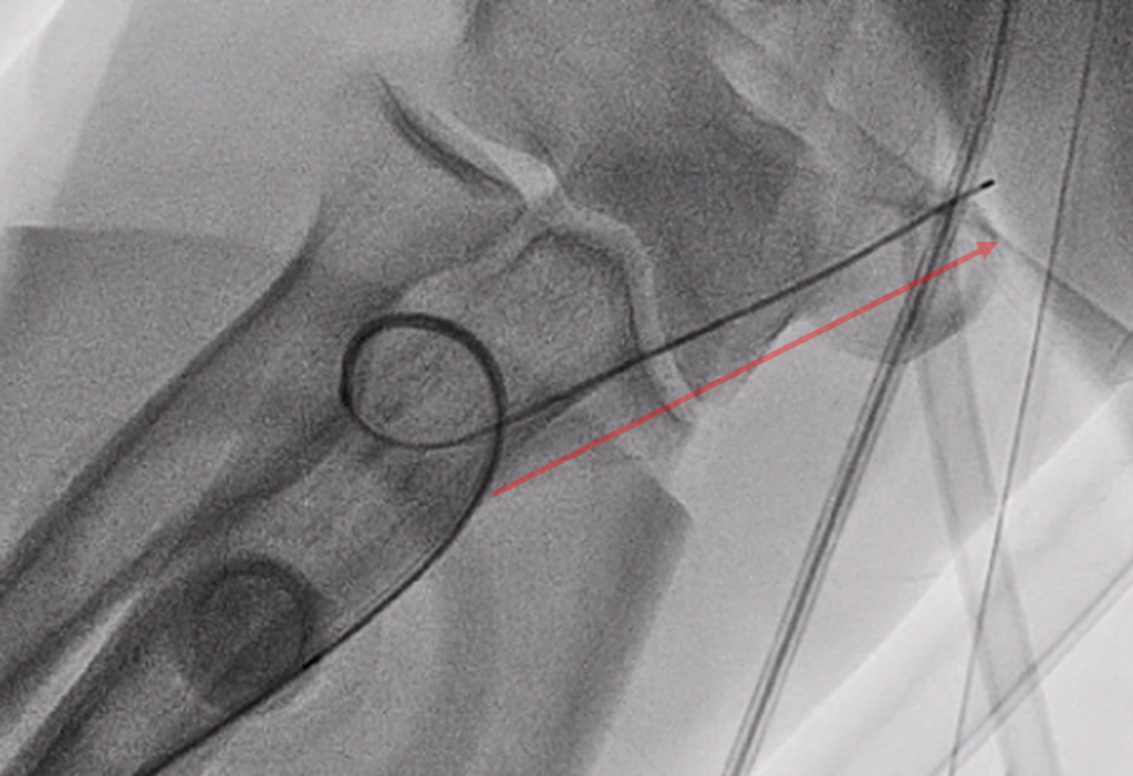
Recording 1 is a fluoroscopy recording of a guide catheter and Silverway set up that is attempted to cross a radial arterial loop. This recording perfectly shows the difference in crossing success between using the high(shaft) or the low(tip) supportive part of Silverway.
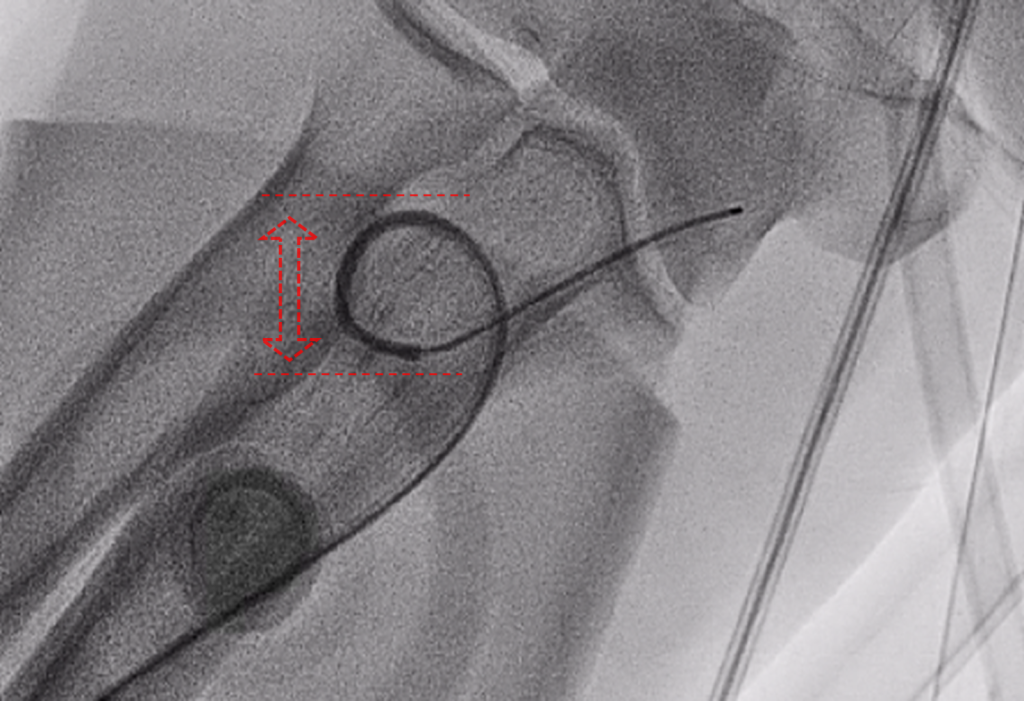
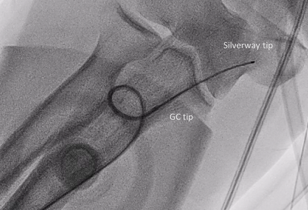
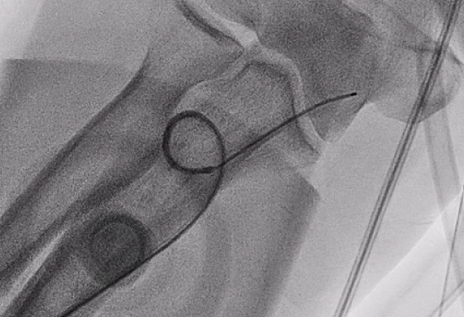
In figure 1, a screenshot of the begin part recording 1, we can see Silverway cannulated in a GC, both traversing a radial arterial loop. In this situation the flexible tip of Silverway is still partially in the GC tip and the radial loop. Due this position, the set up has little support provided by Silverway for crossing the radial loop. Figure 2 and 3 are showing the effect when the GC is tried to be moved forward; the radial loop’s radius increase as the GC cannot track forward due to little support. We can even see the effect of continuous pushing with little support in figure 4, under the applied push force the radial loop tilts.
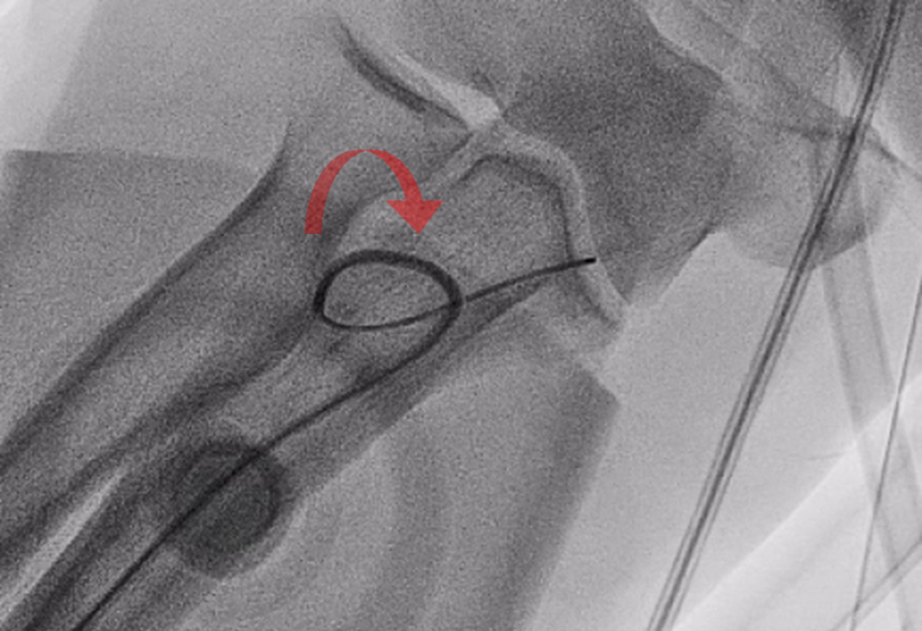
Figure 5 and 6 are elegantly showing what happens when the supportive part of Silverway is placed at the tip of the GC, thus positioning the flexible tip in front of the GC. As result of the optimal placement of Silverway, the GC could successfully cross the radial arterial loop.

K21292_C_LC_1.0